One option is to. Valley fill with passive PFC circuits B and active PFC shown C.

Valley Fill Circuit Wikipedia
Due to the discontinuities from 0 to 30 and from 150 to 210 substantial.

. Product Fill Valve Two main fill valves Figure 3 are located directly in front of the cryogenic vessel and are labeled as gas and liquid The gas fill valve connects to the top of the tank and allows filling into the gas phase. While the circuitry appears very simple the design of an effective correction system is actually. Derive raw dc voltage from the utility a line figure above.
The original valley-fill current shaper permits input current conduction from 30 to 150 and then from 210 to 330. The figure D are this novel PFC and regulation methodology. 408 263 7171 Facsimile.
A valley-fill circuit is a type of passive power factor correction PFC circuitFor purposes of illustration a basic full-wave diode-bridge rectifier is shown in the first stage which converts the AC input voltage to a DC voltage. Observe how the ac supply current looks more sinusoidal that the other circuit I made to compare with rectifier no pfc which can only draw current when the dc side voltage is 2 diode drops. 3 -50 Valley Fill Passive PFC Circuit Although the circuit presents a reasonably good Power Factor 095 and the harmonics can be tamed by the L-C input filter the major shortcoming of this circuit is the 50 bus ripple voltage which in a typical ballast circuit results in a crest factor exceeding 21.
A 03 May 2013. The proposed LED driver achieves high input power. Current waveform of the passive PFC valley fill circuit.
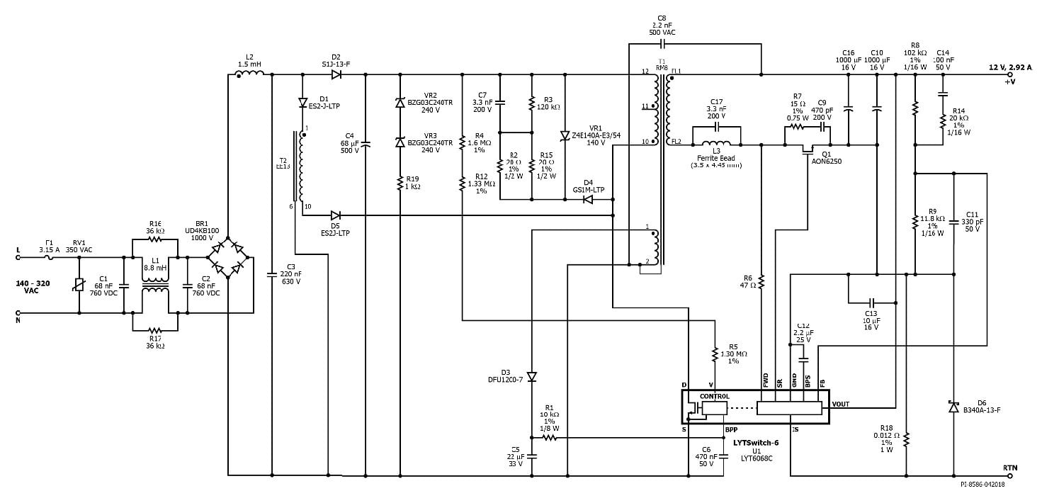
We would like to show you a description here but the site wont allow us. Improved Valley-Fill Passive Current Shaper. 41 Input EMI Filter and Rectifier The input fuse F1 provides safety protection from component failures.
Solving the automotive EMI issues in new cars with all the screens. The goal of this design is to implement a low-cost linear ballast with good PFC acceptable THD and low current-crest factor. We can call Valley Fill Passive Power Factor Correction method in easy term as Valley Fill Circuit.
The Valley fill concept is applied to reduce the output voltage ripple of LED driver. IC is configured to drive a 35 W flyback power supply with a switched valley fill PFC providing a high power factor 12 V constant voltage supply throughout the input range of 140 VAC to 320 VAC. AN-1656 Design Challenges of Switching LED Drivers Rev.
Valley-Fill PFC Circuit. This paper presents the design and analysis of an integrated LC 3 Valley fill passive LED driver suitable for HBLEDs. This application note describes a CFL ballast using valley fill passive PFC circuit and IR2520D ballast control IC.
Its simple to implement but is only suitable where a very high effective ripple voltage on the DC output can be tolerated. The key to this is not allowing the control loop to correct for output ripple by holding the feedback input at a constant level with respect to the line frequency. Valley Fill Passive Power Factor Correction method or Valley Fill circuit is generally a circuit of two electrolytic capacitors a resistor and two diodes.
For low power applications theres a rectifier circuit known as a valley-fill rectifier. With a valley fill circuit. Box 361110 Milpitas California 95036-1110 Telephone.
A valley-fill power factor correction circuit includes a rectifying circuit connected to a charge storage circuit. Single or dual circuit configurations with scroll compressors Automatic compressor staging for capacity control. We would like to show you a description here but the site wont allow us.
As mentioned above the input current must be kept to a nearly sinusoidal shape to achieve high power factor. There is a voltage doubler circuit disposed between the rectifying circuit and the. It is a passive power factor correction circuit I think I found it on Wikipedia.
The liquid fill valve connects to the bottom of the tank and allows filling into the liquid phase. Take better selfies with innovative LED flashes. Published 8 years ago.
A new Circuit for Low-Cost Electronic Ballast Passive Valley Fill with additional Control Circuits for Low Total Harmonic Distortion and Low Crest Factor by Cecilia Contenti Peter Green Tom Ribarich Abstract. The intend of the Valley Fill Passive Power Factor Correction method is to let the power converter to pull power straight off the AC line. DER-857 is a low-line input flyback converter design added with a switched valley-fill PFC circuit.
Through the PFC circuit the design meets the high power factor requirement in LED lighting application while reducing loss by direct energy transfer. The key design goals were high efficiency and high power factor across the input voltage range. 120Vac Valley Fill Buck Triac Dimmable LED Driver.
Design is the Difference SM. This ballast design achieves high power factor 09 low THD. Valley fill approach is added with LC 3 characteristics to further enhance the performance of the LC 3-based LED driver.
Automatic fill low water level reservoir indication and system shutdown Evaporator strainers manifold and isolation valves.

File Valley Fill Circuit Schematic 1 Png Wikipedia

Low Cost Dimmable Led Ballast Using The Valley Fill Current Shaping Circuit
Valley Fill Circuit Semantic Scholar

Pdf High Power Factor Correction Circuit Using Valley Charge Pumping For Low Cost Electronic Ballasts Semantic Scholar

Valley Fill Passive Power Factor Correction Method Power Electronics Talks

File Valley Fill Circuit Svg Wikimedia Commons
Proposed Valley Fill Power Factor Corrector Circuit Download Scientific Diagram
35w Isolated Flyback With Switched Valley Fill Pfc Reference Design New Industry Products
0 comments
Post a Comment